Loops in SIL Toolbox represent safety functions with SIL requirements. They are starting point for SIL calculation. All tags and instruments are assigned to loops. Instruments are used in SIL calculations according loop structures.
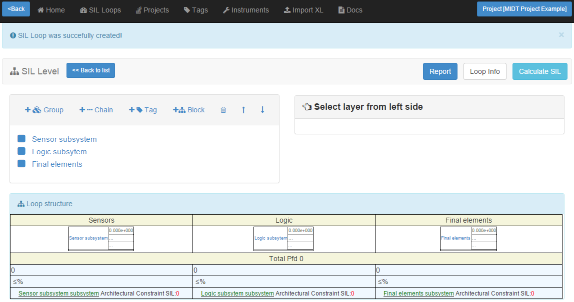
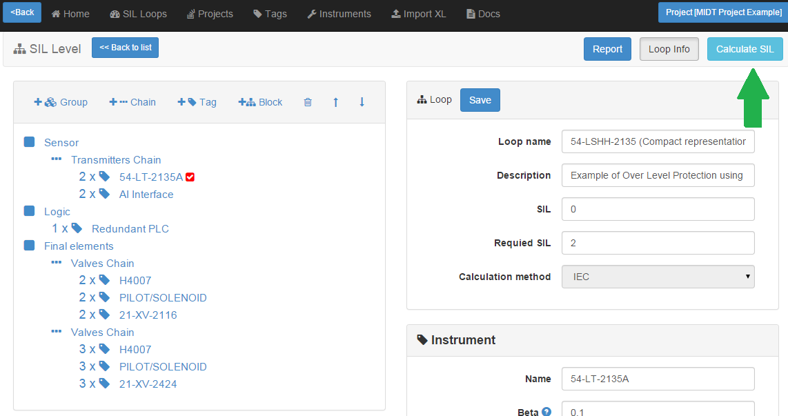
When you have created new loop or started editing existing one, you will be redirected to loop structure page:
Note! Loop creation is described in Loops help page.
The main idea is represent a loop structure as a TREE
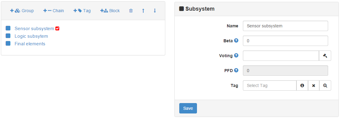
In left panel, you see 3 subsystems: sensors. logic and final elements. Clicking on the subsystem, you will see a red marker and expanded panel from right side. Red marker means what element is selected.
On the the right side you see parameters of selected element.
There are 3 element types: Group, Chain, Tag.
- Group is a group of elements with voting NooM. Group can contains any child elements. An example of group can be 3 transmitters configured in 2oo3 voting.
- Chain is a group of elements with voting NooN. Chain can contains any child elements. Example of chain is Solenoid Driver->Solenoid->Valve. All elements of chain are activated consequently to achieve safety function. Malfunction of any part of chain will lead to loss of whole chain function.
- Tag - is a instrument or group of similar instruments with voting NooN. Tag can't contain any child elements. When voting is set different from 1oo1, tag is interpreted as Group of similar instruments.
Selecting elements you can add childs elements 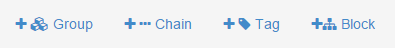
So, using this simple operations you can construcn loop af any difficulty.
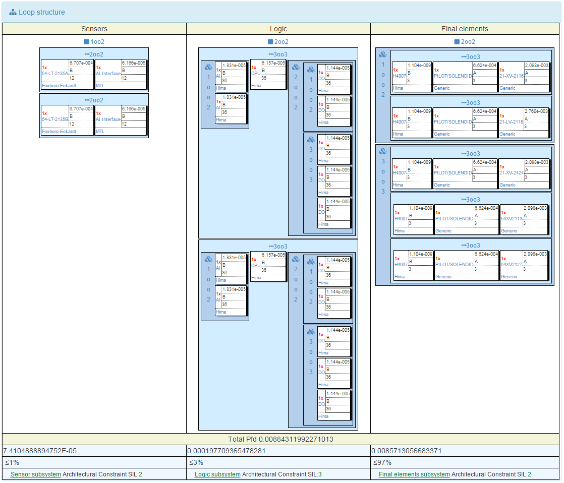
In the bottom part you see loop visualization.
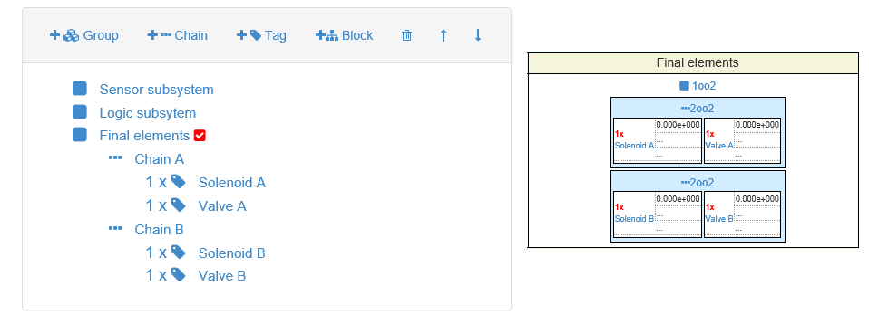
Same loop could be created in different ways. For example, if loop's final element subsystem is represented by 2 valves with solenoids configured into 1oo2 voting, loop can be configured in following ways:
1. Two channels of final elements are configured as chains. Chains are put into final element subsystem (as already metioned, subsystem is interpreted as Group). Subsystem's voting is set to 1oo2 - it is voting between child elements. All tags has voting 1oo1.
Note! Tags has voting 1oo1, because voting 1oo2 is set for group of chains. For Groups and Subsystems voting represent voting between child elements. If voting is set for tag - tag is interpreted as Group, containg a number of similar instruments.
- This representation way is usual ind intuitive.
- It allows to assign different instruments and tag info for different channels of equipment.
- Calculation is first performed for chains. When PFD for chains was calculated, calculation for subsystem (group) is performed. This approach makes impossible using different Beta values for calculating voting between solenoid drivers and between valves. One Beta, defined in subsystem (group) is used. But as practice shows, in many projects it is normal approach to define fixed worst case Beta for whole project.
2. If both channels are identical, loop can be represented in more compact way. Tags are configured in 1oo2 votings and put to one chain. Subsystem's voting is set to 1oo1 - it contains only one chain. All tags has voting 1oo2.
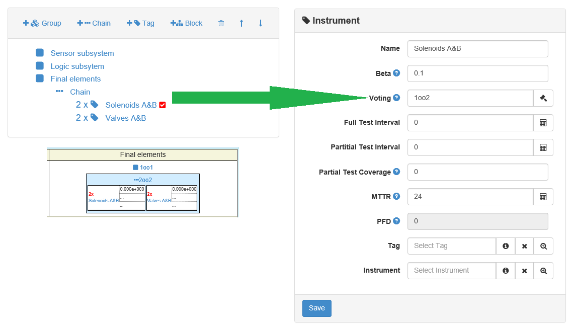
- This representation way is compact and easier to create.
- Calculation is first performed for tags with votings. This approach makes possible using different Beta values for calculating voting between solenoid drivers and between valves.
- Different instruments or tag info can not be assigned for different channels of equipment, because both channels are using same tags in loop structure.
3. Solenoids and valves could be represented as different groups. Groups are configured in 1oo2 votings and put to one chain. Subsystem's voting is set to 1oo1 - it contains only one chain. All tags has voting 1oo1.
Note! Tags has voting 1oo1, because voting 1oo2 is set for groups of tags. For Groups and Subsystems voting represent voting between child elements. If voting is set for tag - tag is interpreted as Group, containg a number of similar instruments.
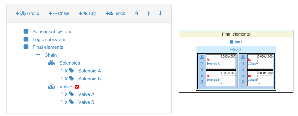
- Calculation is first performed for groups with votings. This approach makes possible using different Beta values for calculating voting between solenoid drivers and between valves.
- It allows to assign different instruments and tag info for different channels of equipment.
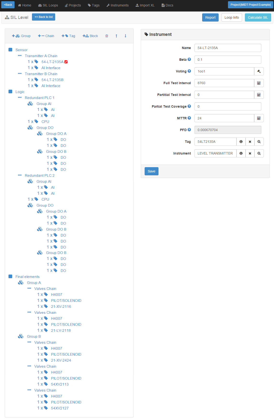
Every component of loop structure has it's own information fields. This information is used in SIL calculations:
- Common cause failure Beta. During calculation solution tries to take Beta value from loop component properties. If Beta value for component is not defined by user, Beta is taken from project properties (general assumed Beta value, commonly 10% is used as worst case scenario).
- Mean Time to Restoration MTTR. In most cases the safety function must be switched to the safe state immediately. During calculation solution tries to take MTTR value from loop component properties. If MTTR value for component is not defined by user, MTTR is taken from project properties
- Test interval Tfull should be defined by user for every loop component, which has assigned instrument.
- Partial test interval Tpartial (for example partial stroke test of valve) can be defined by user in component properties, while designing loop. If partial test interval is undefined, solution assumes, that only full test is performed.
- Test Coverage TC. The TC is an indicator for the quality of partial testing. If partial test interval is defined by user in loop component properties, test coverage must be also defined.
- Voting is defined by user in loop component properties. Voting could be defined for “Tag”, “Group” and “Subsystem” type elements.
After creating loop structure, You can calculate a SIL level:
Calculations:
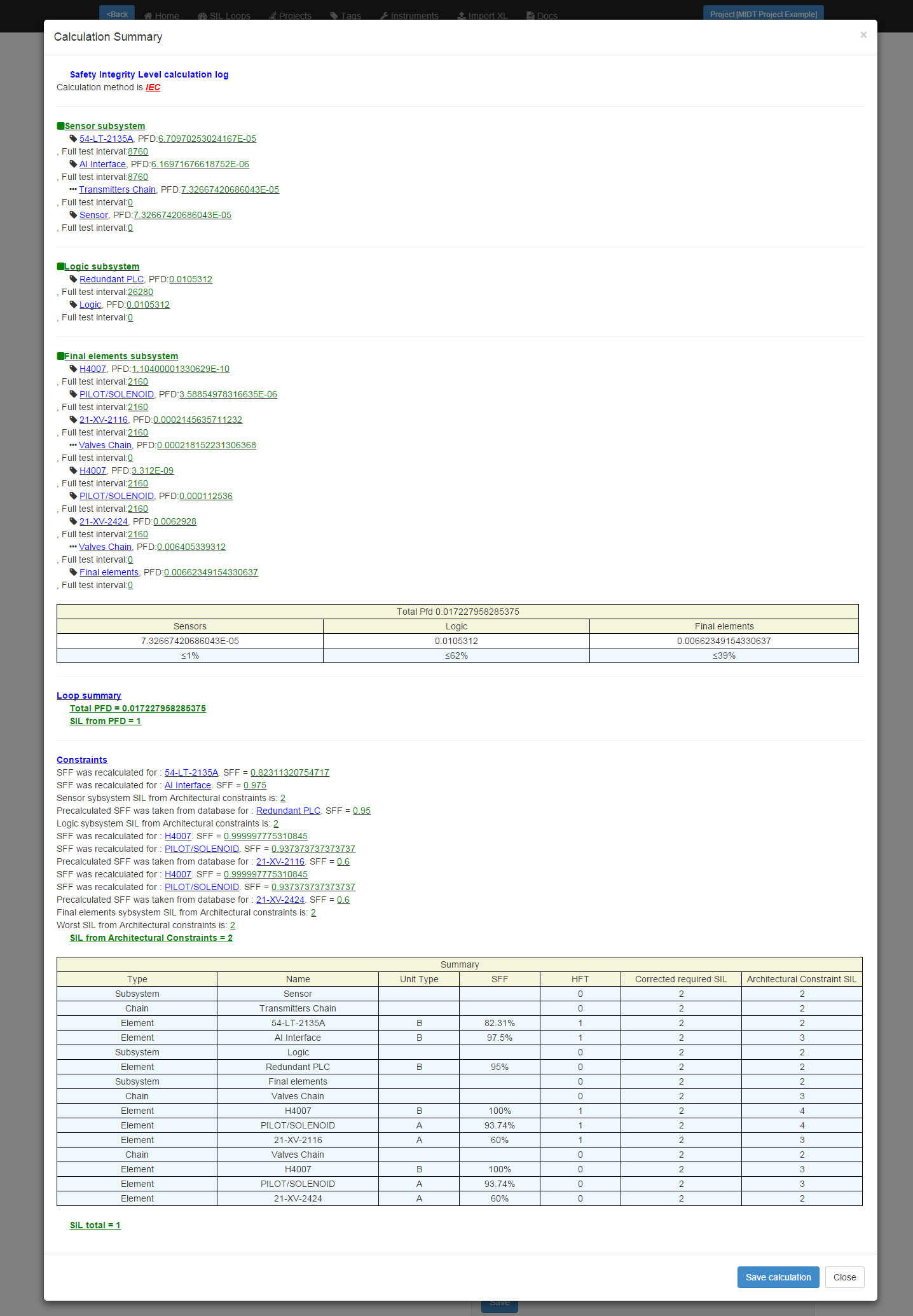
Press "Save" button, to save element's PFDs and Loop's SIL property!