Preface
Architectural constraints SIL calculation is simple enough, when calculations are performed by engineer in analytical way. But when we want to automate this task, the challenge arises, which algorithm to choose for calculation of architectural constraints for loop of any complexity and any structure. In this article we describe, how SIL from architectural constraints is calculated in SIL Toolbox. If you know better or more accurate way to perform this task, please comment this article or contact us at
sil@midt.no
Basic architectural constrains concepts
Safe Failure Fraction (SFF) – the fraction of failures which can be considered “safe” because they are detected by diagnostic tests or do not cause loss of the safety function.
In SIL Toolbox during calculation of SIL solution checks for every part of loop if all necessary data for SFF calculation is present in assigned instrument properties. SFF is calculated for every instrument using formula:
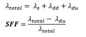
If assigned instrument do not contain needed reliability data (for example only ?du is present), solution takes precalculated (entered by user or contained in generic instruments) SFF value. In this case "Precalculated SFF was taken from database” message will appear in calculation log.
If assigned instrument don’t contain needed reliability data and SFF, architectural constraints will not be analysed and you will be informed in calculation log.
Hardware Fault Tolerance (HFT) determines, how many faults can occur before losing safety function. HFT is calculated for combinations of elements with voting MooN:
HFT = N – M
Unit type is contained in assigned instrument properties. If Unit type is not entered by user, it is assumed to be B type (worst case).
For type A elements all possible failure modes can be determined for all constituent components, whereas for type B elements the behavior under fault conditions cannot be completely determined. In general type B components contain microprocessor, complex electronics and software, while type A components are electromechanical.
Architectural constraints SIL calculation
Architectural constraints SIL calculation is started from lowest level elements (i.e. tags with assigned instruments). When all lowest level instrument architectural constraints SIL have been calculated, solution starts calculating of higher level groups/subsystems until whole loop is covered.
Following rules apply for different types of structures.
For simple elements architectural constraints SIL is calculated from SFF, HFT and unit type data using following tables:
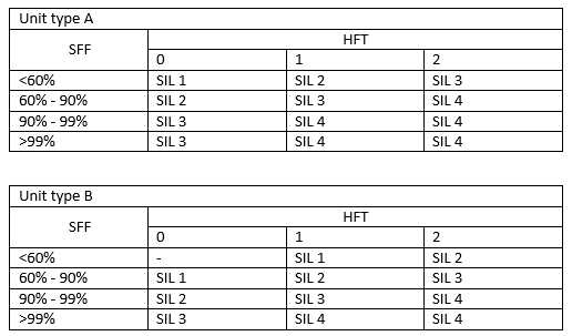
For chains of elements solution searches for element with lowest architectural constraints SIL. Such element restricts whole chains performance.
For groups and subsystems solution searches for element with lowest architectural constraints SIL. This value is increased by HFT calculated from group’s voting.
Finally, when all subsystems have their architectural constraints SIL calculated, lowest SIL is taken as whole loop’s architectural constraints SIL, exactly as it is done for chains.
Example calculation of architectural constraints
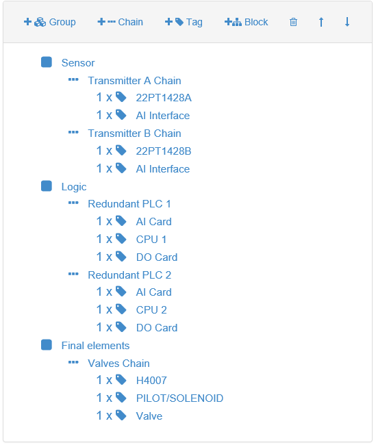
Following loop represents PAHH protection with closing of one valve. It contains 2 pressure transmitters with interfaces, configured in 1oo2 voting, redundant PLC (2oo2) and final element – valve with solenoid and solenoid driver.
Loop tree:
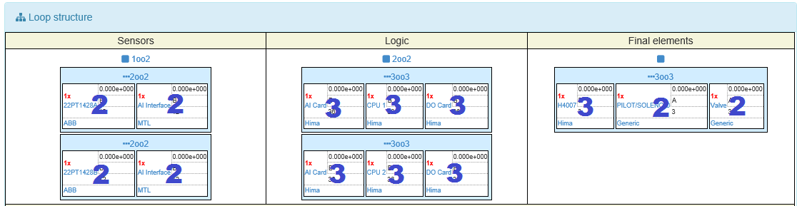
Loop structure:
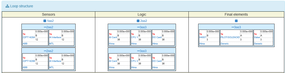
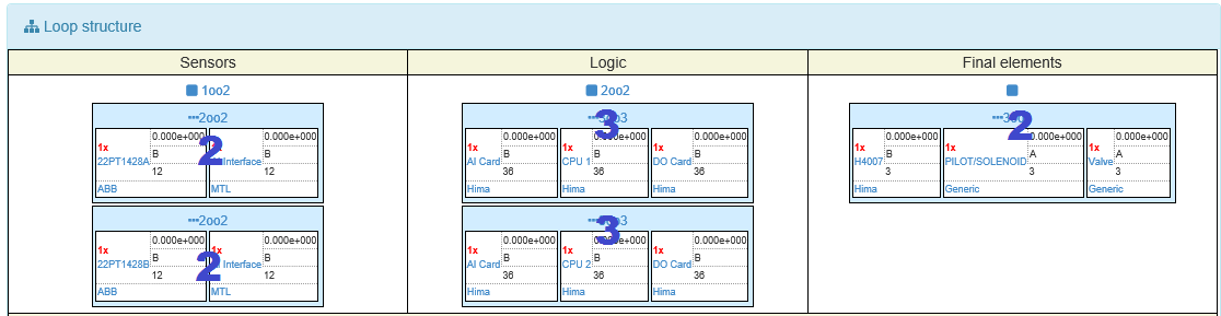
Calculation is starting from lowest level elements, i.e. transmitters, CPU, solenoids, valves. All elements receive their preliminary architectural constraints SIL level:
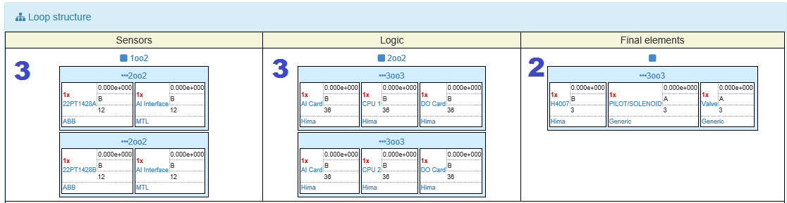
Finally, minimal architectural constraints SIL from all subsystems is chosen. It is whole loop’s architectural constraints SIL. In this example it is SIL 2.
In this example it is obvious, that analytically SIL level 3 for transmitters can be chosen at first step (engineer see, that voting for transmitters is 1oo2). But more complex approach with group/chain levels provide possibility to automatically calculate architectural constraints SIL for more sophisticated loop architectures.
Architectural constraints SIL for all level elements are present in calculation report:
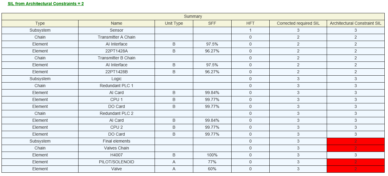
Elements, that restrict architectural constraints SIL level below required (for this example required SIL 3 was taken), are marked red at all levels.
Feel free to leave comments and suggestions, project is in development phase and any feedback could help make solution more suitable for your needs.